Low-Temperature Belt Dryer
DLT Series
Transform Your Biosolids Management
The Centrisys/CNP DLT Series – the smart choice for
efficient, safe, and cost-effective sludge drying. Our innovative solution addresses the complex challenges of modern wastewater treatment, offering a pathway to improved operations and reduced costs.
- Reduced Sludge Volume up to 80%
Lower transportation and disposal costs as
the DLT addresses one of the most pressing
challenges in wastewater treatment offering
significant operational savings and a smaller
environmental footprint. -
Simplified Maintenance
By eliminating the need for confined space entry, we reduce maintenance time and costs, improve safety, and minimize the need for specialized training or equipment.
- Enhanced 24/7 Operational Efficiency
Maximizing throughput with minimal operator
attention, the DLT optimizes labor resources
and improves plant productivity ensuring
consistent performance and reduces the need
for frequent start-ups and shutdowns. -
Improved Safety (NFPA 820/654 compliant)
Our design mitigates risks associated with biosolids processing, safeguarding operators and reducing
potential liabilities.
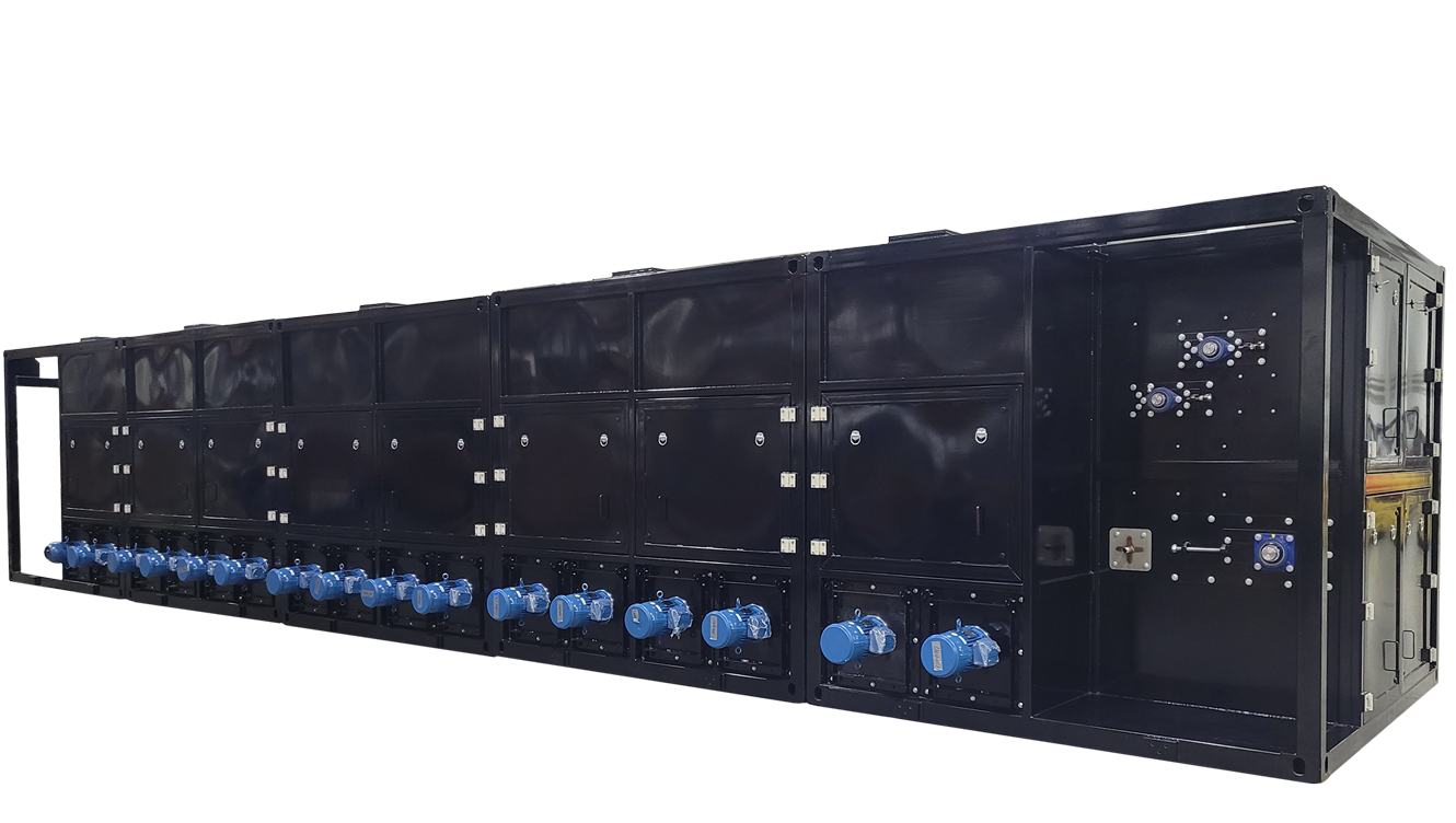
Modular Design
Integrated Heat Recovery System
Compact Footprint
Class A Biosolids Production
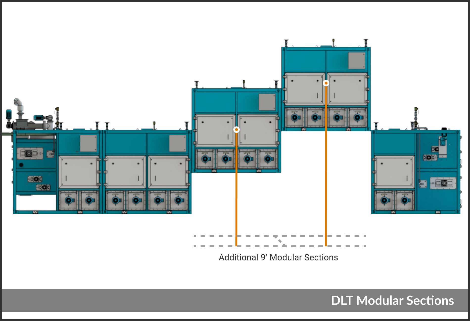
Modular Design
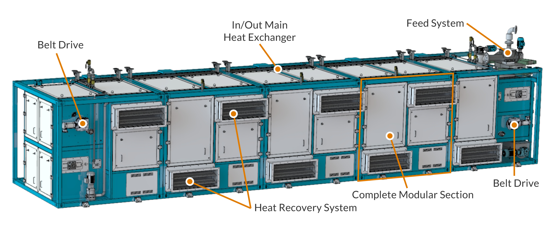
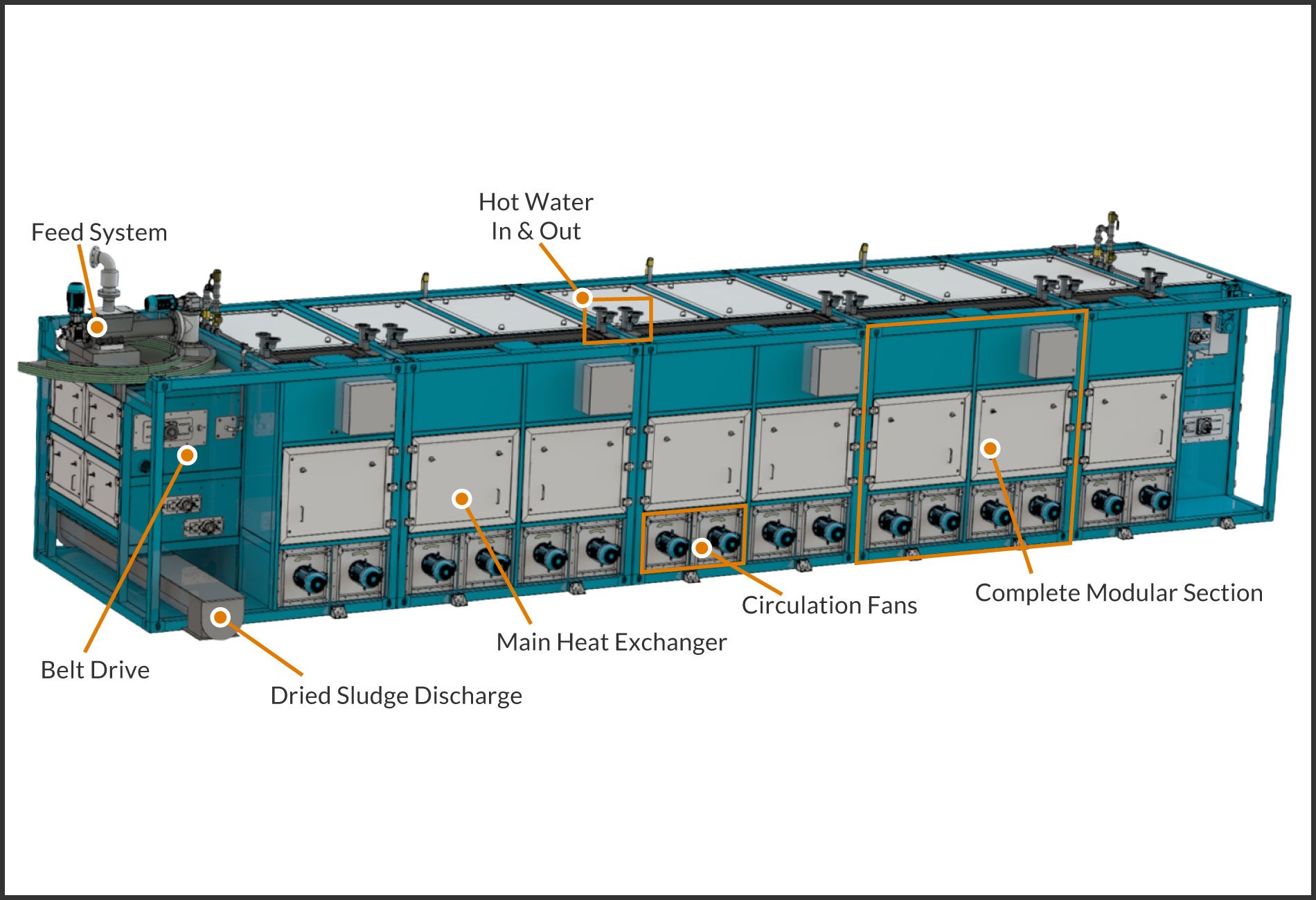
- Our scalable design (1-6 heat segments, 200-2,000 lb H2O/hr evaporation) allows for future expansion, reducing initial capital costs while providing flexibility for growing needs protecting your investment but also facilitates easier maintenance and minimizes downtime during repairs.
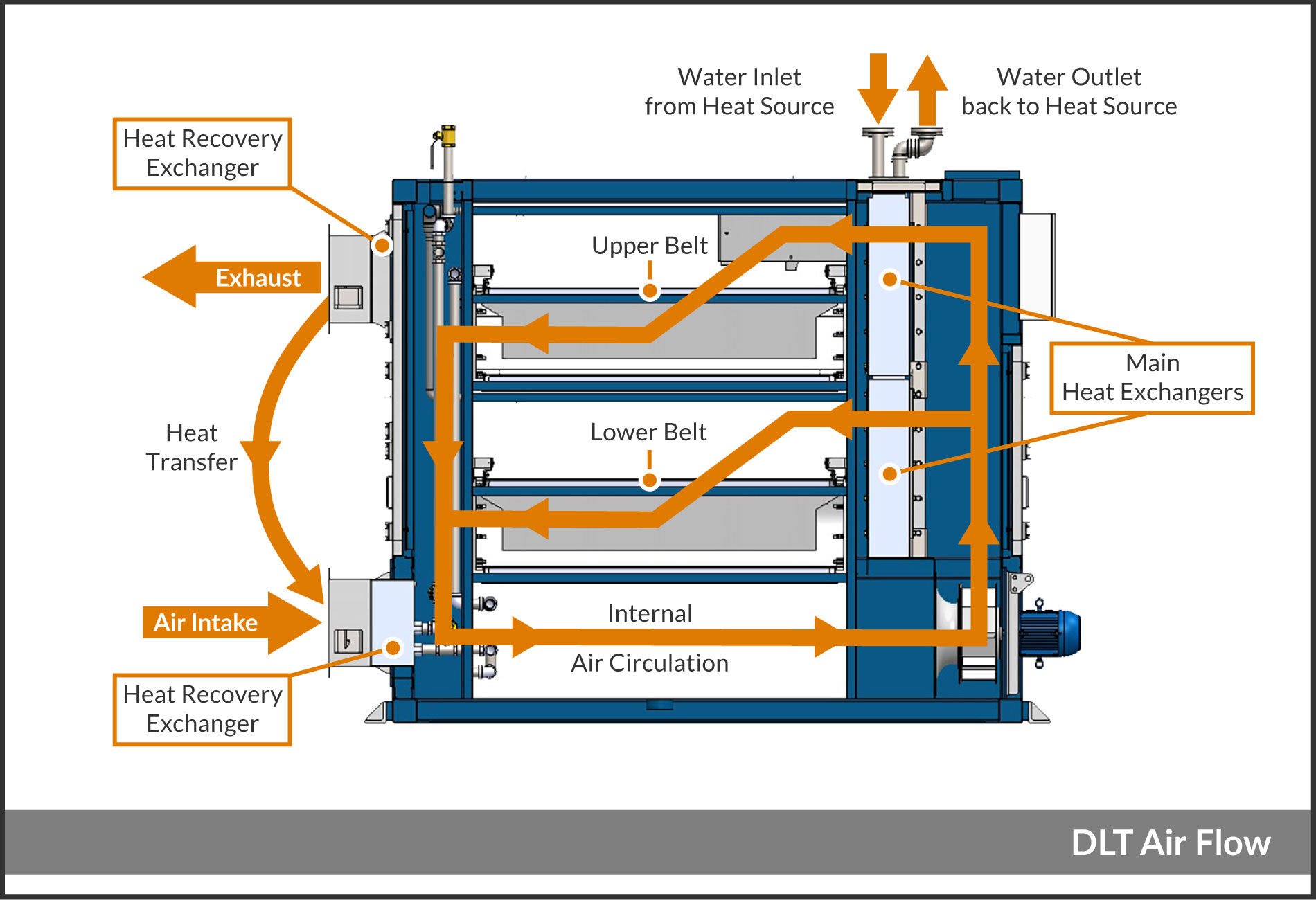
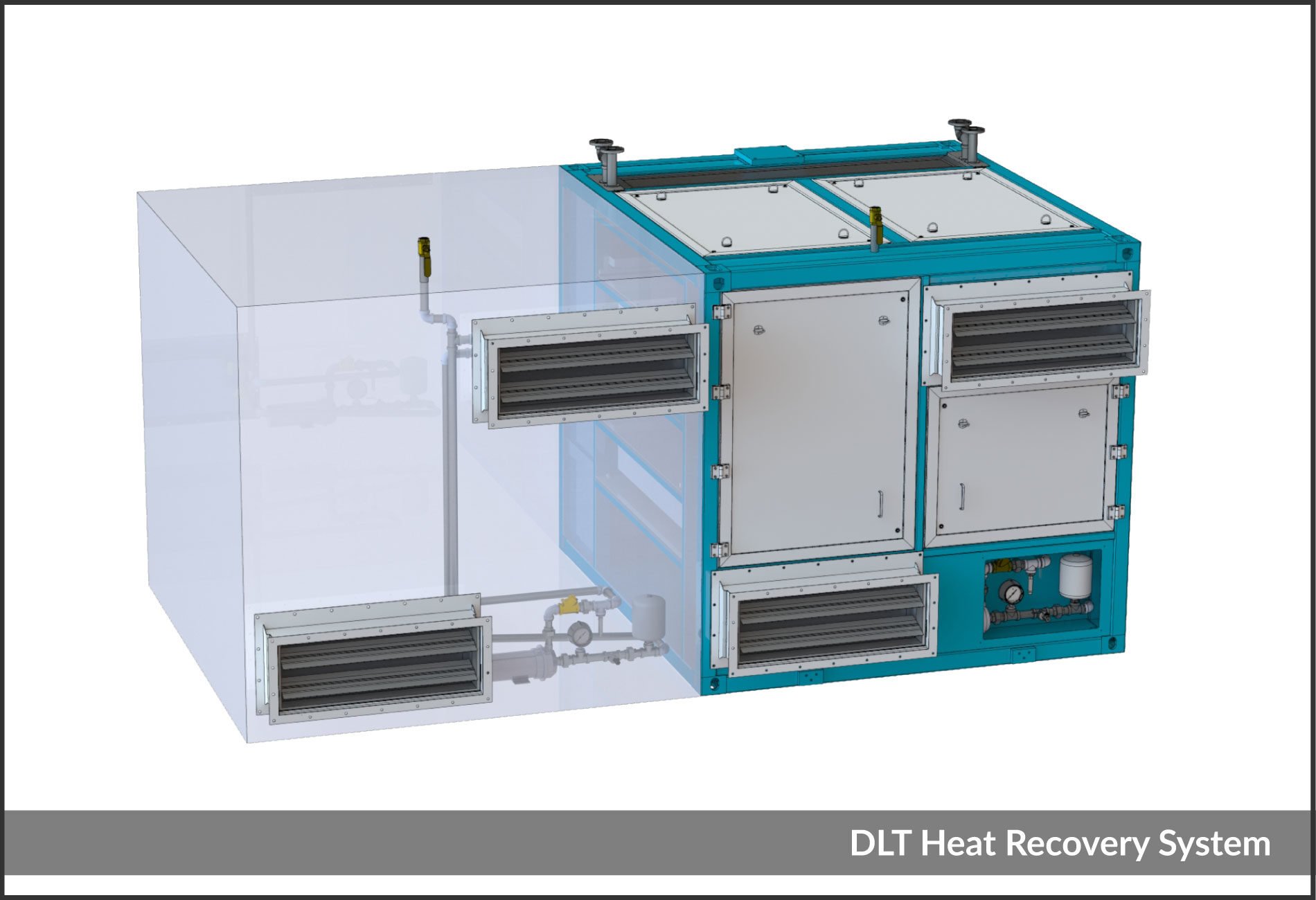
Integrated Heat Recovery System
- By recapturing and reusing heat, our system significantly improves energy efficiency, cutting operational costs eliminating single points of failure, enhancing overall system reliability and ensuring continuous operation even during maintenance.
Compact Footprint
-
The low-profile design enables installation in existing structures, saving on new construction costs while preserving valuable plant space for other processes. This flexibility is crucial for facilities with space constraints or those planning for future expansions.
Class A Biosolids Production
-
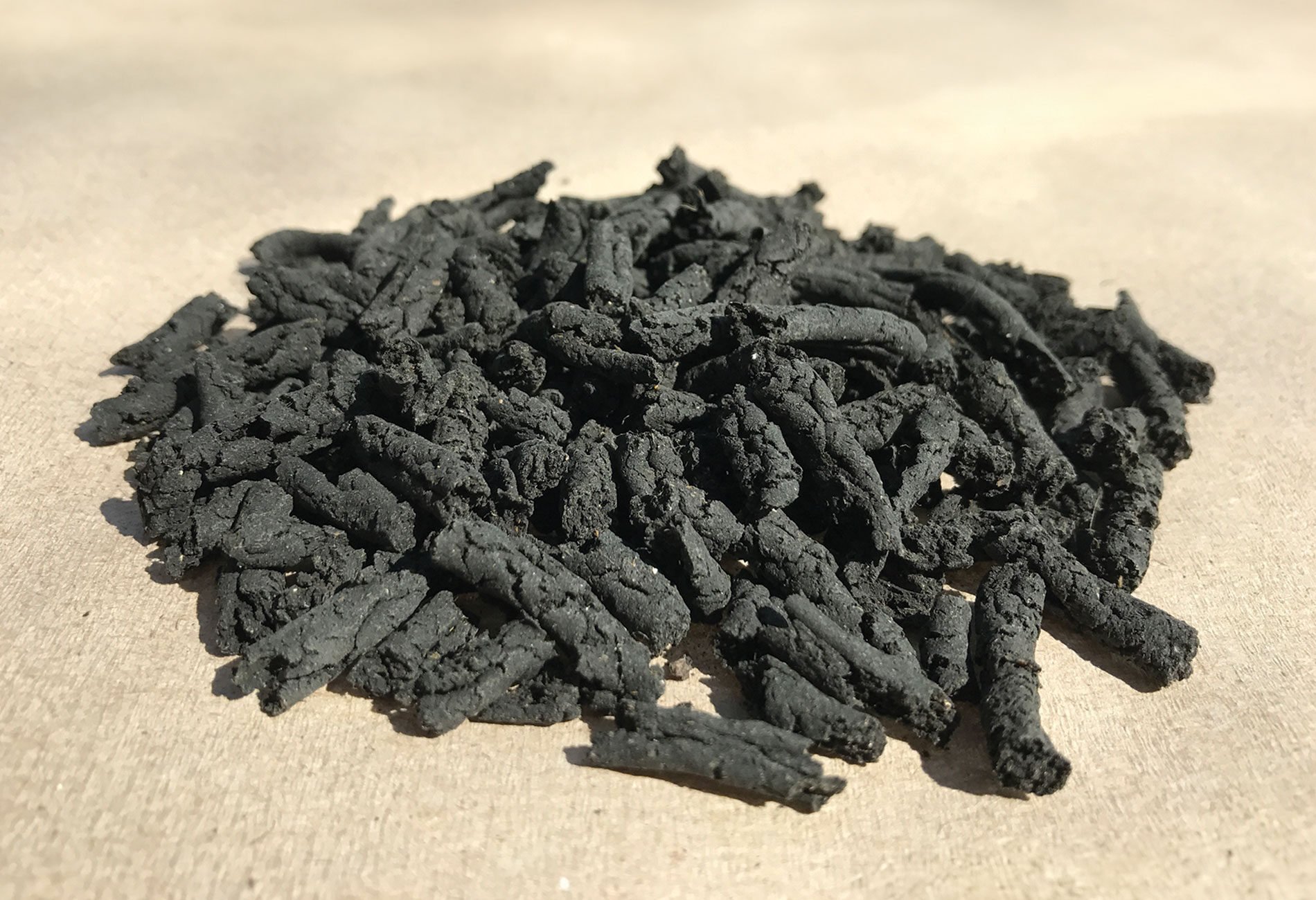
Meeting stringent regulatory requirements for pathogen reduction, the DLT opens up more options for beneficial reuse of biosolids with up to 194 F (90 C) internal temperature. This capability not only ensures compliance but also potentially creates new revenue streams for your facility.
Low-Temperature Belt Dryer
| DLT120 | DLT220 | DLT320 | DLT420 | DLT520 | DLT620 | |
|---|---|---|---|---|---|---|
| Number of Heat Segments | 1 | 2 | 3 | 4 | 5 | 6 |
|
Max H2O Evaporation lb H20/hr (kg H20/hr) |
315 (143) |
630 (286) |
945 (429) |
1,260 (572) |
1,580 (717) |
1,900 (860) |
|
Process Capacity* short tone/day (meter tons/day) |
5-6 (4.4-5.5) |
10-11.5 (9-10.5) |
14-17 (12.7-15.4) |
19.5-22.7 (17.6-20.6) |
24-28 (22-25.5) |
29-34 (26.4-30.8) |
|
Height without foundation ft-in (m) with foundation |
11-8 (3.6) 13-4 (4.1) |
11-8 (3.6) 13-4 (4.1) |
11-8 (3.6) 13-4 (4.1) |
11-8 (3.6) 13-4 (4.1) |
11-8 (3.6) 13-4 (4.1) |
11-8 (3.6) 13-4 (4.1) |
|
Width ft (m) |
12 (3.7) |
12 (3.7) |
12 (3.7) |
12 (3.7) |
12 (3.7) |
12 (3.7) |
|
Length ft-in (m) |
21-4 (6.5) |
30-4 (9.25) |
39-4 (12) |
49-4 (14.75) |
57-4 (17.5) |
66-4 (20.2) |
|
Clearance ft (m) |
4 (1.2) |
4 (1.2) |
4 (1.2) |
4 (1.2) |
4 (1.2) |
4 (1.2) |
| Number of Heat Segments | 1 |
| Max H2O Evaporation lb H20/hr (kg H20/hr) |
315 (143) |
| Process Capacity* short tone/day (meter tons/day) |
5-6 (4.4-5.5) |
| Height without foundation ft-in (m) with foundation |
11-8 (3.6) 13-4 (4.1) |
| Width ft (m) |
12 (3.7) |
| Length ft-in (m) |
21-4 (6.5) |
| Clearance ft (m) |
4 (1.2) |
| Number of Heat Segments | 2 |
| Max H2O Evaporation lb H20/hr (kg H20/hr) |
630 (286) |
| Process Capacity* short tone/day (meter tons/day) |
10-11.5 (9-10.5) |
| Height without foundation ft-in (m) with foundation |
11-8 (3.6) 13-4 (4.1) |
| Width ft (m) |
12 (3.7) |
| Length ft-in (m) |
30-4 (9.25) |
| Clearance ft (m) |
4 (1.2) |
| Number of Heat Segments | 3 |
| Max H2O Evaporation lb H20/hr (kg H20/hr) |
945 (429) |
| Process Capacity* short tone/day (meter tons/day) |
14-17 (12.7-15.4) |
| Height without foundation ft-in (m) with foundation |
11-8 (3.6) 13-4 (4.1) |
| Width ft (m) |
12 (3.7) |
| Length ft-in (m) |
39-4 (12) |
| Clearance ft (m) |
4 (1.2) |
| Number of Heat Segments | 4 |
| Max H2O Evaporation lb H20/hr (kg H20/hr) |
1,260 (572) |
| Process Capacity* short tone/day (meter tons/day) |
19.5-22.7 (17.6-20.6) |
| Height without foundation ft-in (m) with foundation |
11-8 (3.6) 13-4 (4.1) |
| Width ft (m) |
12 (3.7) |
| Length ft-in (m) |
49-4 (14.75) |
| Clearance ft (m) |
4 (1.2) |
| Number of Heat Segments | 5 |
| Max H2O Evaporation lb H20/hr (kg H20/hr) |
1,580 (717) |
| Process Capacity* short tone/day (meter tons/day) |
24-28 (22-25.5) |
| Height without foundation ft-in (m) with foundation |
11-8 (3.6) 13-4 (4.1) |
| Width ft (m) |
12 (3.7) |
| Length ft-in (m) |
57-4 (17.5) |
| Clearance ft (m) |
4 (1.2) |
| Number of Heat Segments | 6 |
| Max H2O Evaporation lb H20/hr (kg H20/hr) |
1,900 (860) |
| Process Capacity* short tone/day (meter tons/day) |
29-34 (26.4-30.8) |
| Height without foundation ft-in (m) with foundation |
11-8 (3.6) 13-4 (4.1) |
| Width ft (m) |
12 (3.7) |
| Length ft-in (m) |
66-4 (20.2) |
| Clearance ft (m) |
4 (1.2) |
Hot Water Temperature In/Out: 194 F (90 C)/158 F (70 C)
Max Internal Temperature: 186 F (86 C)
* Capacity assumes feed sludge at 20-30% DS and 24-hour operation
Technical Highlights
- Hot water temperature: 194 F (90 C) maximum
This optimal temperature balances drying efficiency with safety, operating below flash-ignition temperatures to enhance overall plant safety while maintaining effective drying performance. - Achieves >90% solids content
By maximizing volume reduction and producing a stable, easily manageable end product, our system significantly reduces storage and handling requirements while improving the quality of the final biosolids.
- Optional back-mixing for <18% DS
This feature expands the range of influent sludge characteristics that can be processed, increasing operational flexibility and allowing the system to adapt to varying input conditions.
